 |
|||||||||||||||||||||||||||||||||||||||
|
|
|
Suspension alignment As I work within the car industry, and specifically within the suspension design and development area, I am all too aware of the importance of getting the suspension set up accurately. Suspension alignment relates to the angles of the 4 wheels relative to the road, i.e. the toe angle (the angle of the wheel relative to the straight ahead) and the camber angle (the angle relative to the vertical). It is worth mentioning that before setting up the front end geometry, it is worth checking that the steering rack is centralised. To do this, count the number of turns of the steering wheel from full left lock to full right lock, and then count back from the lockstops half the number of turns. In an ideal world your steering wheel will point straight ahead at this point. If it is significantly off centre, you will need to separate the bottom of the steering column from the splined rack input, and re-attach with the steering wheel centralised. This ensures that you have equal rack travel in each direction. I performed this procedure during the build so did not need to re-check, but it can catch people out. To get the toe roughly setup, I had originally used some long lengths of metal tubing strapped to the wheels protruding beyond the bodywork, and then measured the relative distance between the poles at 2 points. Some trigonometry gives the total toe angle (which is the angle of one wheel relative to the other). Hopefully this diagram (with rather extreme toe in!) expains what I mean:
For the camber I performed a rough check using a spirit level to give a vertical reference, and then used some more trigonometry. Camber settings are generally less critical than toe settings- a general rule of thumb is that the vehicle is ten times more sensitive to toe than camber. Hence, a toe variation of 1 tenth of a degree (or 6 minutes) would be seen as equivalent to varying the camber by a whole degree. This method was OK for getting me through SVA (in fact, I had to mess around with front toe settings to get some degree of steering self-centring, but that's another story...), but given the tolerances we set vehicles up to at work (ideally to within a few minutes tolerance), I was keen to get the Mojo setup properly. Once again, I was lucky in that I had access to a full optical alignment 'Hunter' rig after normal working hours at work! One thing I was keen to investigate was how front toe settings changed the steering feel. Since backing off from the extreme toe settings I used for the SVA test, I had noticed a slightly 'dead' feeling around the straight ahead, followed by a sudden eagerness to turn. This 'two stage' feeling made the car feel quite nervous. I had also noticed a tendency for the car to follow ruts in the road quite violently- the kind you get when HGVs regularly use a route- and this also made the car a little unnerving to drive. So, with the Mojo on the Hunter rig, we pulled off the current setup:
So, the car is setup with a small amount of toe out at the front, and is very assymmetrical in terms of toe at the rear. The camber values are reasonably consistent, so I chose not to adjust them at this stage. As a baseline setup for toe, Jeremy Phillips at Sylva had suggested using Lotus Elise settings. However, this runs with toe out at the front and I wanted to try running with a little toe in to see if this improved the 'dead' feeling. Caterham suggest around 0.3degree toe in for their cars, so I decided to aim for something similar on the front, and aimed for the Elise setting of 22 minutes total toe in at the rear. This is what we ended up with:
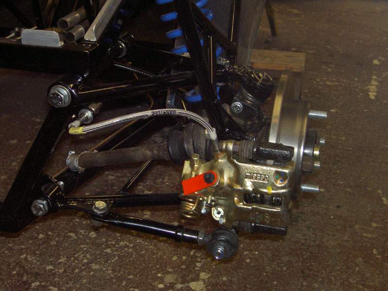
So, the rear toe assymmetry is now pretty much fixed and set up as an Elise, and I'm running with 0.24 degrees of total toe in at the front. Driving impressions with these settings are positive: The 'dead' feel to the steering is now much better, the car responds sooner to steer inputs but is more progressive, and the steering feel once in a bend also seems better. This demonstrates how a change of less than a fifth of a degree on each front wheel can make a difference! Ideally I should have test driven the car after making the first adjustment rather than changing both front and rear toe settings together, but in practice this was going to be a pain- it takes quite a while to get the car setup on the rig. April 2008 Update: One of the few aspects of the Mojo that I felt could be improved upon was the rear toe link arrangement. The toe link runs from a bracket on the lower wishbone to the rear end of the lower upright through-bolt.
On my car, the outer end has a bush as used elsewhere on the suspension, and the inner end is attached to the wishbone with 2 M8 bolts. Adjustment is therefore carried out by releasing the 2 bolts and slotting the holes if necessary. However this is a very imprecise adjustment, normally requires 2 people (one to hold the wheel, one to tighten the nuts) and is prone to being knocked out of position. Adjustment could now be performed by undoing the inner bolt, rotating the link (in half turn increments) and re-attaching the inner bolt. However, this still required the inner bolt to be removed, and so each half turn on the rose joint won't necessarily give equal adjustments due to tolerances inevitable when removing and replacing the bolt.
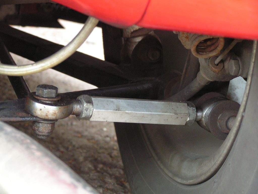
I therefore devised a further improvement to the arrangement, using a similar outer rose joint setup to the later Mojos, but attaching the inner end of the link to the plate on the wishbone with a second rose joint. By making one of these rose joints a left hand threaded item, adjustment can be performed by rotating the link in much the same way as the front trackrod.
|
|||||||||||||||||||||||||||||||||||||
|
|
|||||||||||||||||||||||||||||||||||||||